

Advice
What a twin-wall flue system involves
Understand the parts, route and decisions behind an insulated system chimney for a stove, from connection to terminal and future maintenance.
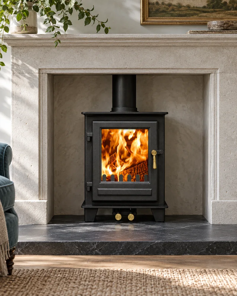
A twin-wall flue is a factory-made insulated chimney system. It is commonly considered when a stove cannot use a suitable existing masonry chimney, but it can also form part of other designed routes. The two metal walls and insulation between them are only the basic construction; the finished chimney includes compatible lengths, bends, supports, penetration components, weathering and a terminal.
Every component belongs to a tested system. The route must be designed for the appliance and building, then installed in line with the system manufacturer’s instructions and the relevant building requirements.
Twin wall and connecting flue pipe are different
The visible pipe immediately above a stove may be a single-wall connecting flue pipe. Its job is to connect the appliance to the main chimney or liner. A twin-wall insulated system chimney performs a different role and may begin at a specified transition point.
Do not assume single-wall pipe can continue through a wall, ceiling, floor or roof. The permitted arrangement and changeover point depend on the appliance, the chimney system and the installation design.
The main parts of a system
A particular project may use only some of the following, but each needs to be considered as part of the route:
- appliance connector or adaptor;
- connecting flue pipe where specified;
- insulated straight lengths;
- bends or offsets kept within the system rules;
- tees or access components where the design requires them;
- wall bands, brackets or structural supports;
- ceiling, floor, wall and roof penetration components;
- fire stops, ventilated plates or protective enclosures;
- roof flashing and storm-weathering details;
- a terminal compatible with the system and location;
- inspection and sweeping access.
Names vary between manufacturers. The useful principle is that these are engineered parts of one chimney rather than a collection of generic tubes.
One system from connection to terminal
Components from different chimney systems should not be casually mixed. They may have different joint designs, tested clearances, wall thicknesses, insulation, support limits and product designations even when their nominal diameter looks identical.
Ask the quotation to name the system manufacturer and product range. Any transition to another approved component should be explicit and supported by the relevant instructions. This also makes future inspection and replacement easier because the installed system can be identified.
Route design comes before the parts list
The route determines which components are needed. A useful design considers:
- a suitable appliance position and hearth;
- the vertical rise and any necessary changes of direction;
- floor, ceiling, wall and roof construction;
- nearby combustible materials;
- windows, doors, roof slopes and neighbouring structures;
- the finished terminal position and height;
- load-bearing support and bracket locations;
- internal enclosures and access for inspection;
- external appearance and safe installation access;
- a practical sweeping and maintenance route.
Manufacturer diagrams are examples, not permission to copy a layout into a different property. Exact dimensions, clearances and support intervals come from the selected system instructions and the site conditions.
Internal versus external appearance
An internal route can become an architectural feature or be enclosed where the approved design requires it. It may pass through rooms above, which affects floor plans and finishing. An external route places more of the system on an outside elevation, with visible brackets and a terminal above roof level.
Finish options can include stainless steel or factory-coated surfaces within a manufacturer’s range. Colour should be chosen after the technical route is settled. Painting an unsuitable component on site is not the same as specifying a tested factory finish.
Openings and making good
The installation can involve work through a wall, ceiling or roof. Ask which trade forms each opening, fits the protective components, completes roof weathering and makes good the surrounding surface. If scaffolding or specialist access is required, it should be visible in the scope.
This is especially important when a stove installer, roofer, builder and decorator are involved. A written sequence prevents an opening being formed before the final system and route are confirmed.
Performance and maintenance
Insulation helps the chimney maintain suitable flue-gas conditions, but the appliance still needs to be operated and maintained correctly. Use only permitted fuel, follow the appliance instructions and arrange the appropriate sweeping and inspection.
The system should remain identifiable. Keep the product information, route details, installation records and any guarantee registration together. Ask how the system is accessed for sweeping and what external or internal signs should prompt professional advice.
Questions to settle before installation
- Which exact chimney system has been specified and why?
- What is its full product designation and internal diameter?
- Where does the insulated section begin?
- Where will it pass through the building and how are those points protected?
- Which bends, supports and brackets are required?
- How is the roof or wall penetration weathered?
- Where will the terminal sit in relation to the building?
- How will the system be swept and inspected?
- Who handles access equipment, openings and making good?
- What records, notification and warranty information will be handed over?
Connect the system to the wider project
Read installing a stove without an existing chimney for the property decision, then use the twin-wall flue installation page to frame the enquiry. The appliance, hearth, system chimney and room finish should appear in one installation plan before work begins.
Sources checked
General guidance checked on 16 September 2026 against:
- GOV.UK: Approved Document J for combustion appliances, flues and protection of buildings
- BFCMA: wood-burning installation guide and system-chimney diagrams
- Schiedel: system-chimney and liner selection guide
- Schiedel: installation instructions for manufactured flue systems
The links explain general principles and example systems. The exact route, components, clearances and terminal must be determined from the selected system, appliance and property assessment.
Continue planning
Related buyer guides
Can you install a stove without an existing chimney?
See how an insulated system chimney may create a route for a stove and which room, building and external details must be assessed first.
02Choosing fireplace chambers and hearths
Plan the opening, chamber lining, hearth material and proportions around the fire or stove, with the technical specification checked for the exact appliance.
03What to expect from a stove installation
Follow the usual decisions from first showroom conversation to property assessment, written scope, installation and handover.
A simple first step
Ask about your room
Tell us what you have in mind. The showroom team will be in touch shortly.
Prefer to talk? Call 01625 402900.